ABSTRACT
Ethane crackers are subject to severe operating conditions that pose reliability issues and require high maintenance which can have a significant impact on the operational and maintenance cost. Damage mechanisms associated with Ethane crackers and associated piping and fixed equipment include carburization, creep, erosion, thermal fatigue, sigma phase embrittlement, stress relaxation cracking, oxidation, and general corrosion among others. Factors such as high operating temperatures, coke buildup, decoking practices, unexpected shutdowns, and operational breaches can induce or enhance the severity of the damage mechanisms and reduce equipment life. Therefore special attention is needed to avoid unexpected catastrophic failures while optimizing equipment performance.
Risk Based Inspection (RBI) methodology incorporating a damage mechanism review (DMR) can be used to manage the assets in Ethane crackers and reduce the risk of loss of containment by identifying the damage mechanisms that are expected to occur in each fixed equipment and piping component, calculating the risk associated with a potential loss of containment, and clearly defining inspection plans based on the RBI assessment results.
Since day to day changes in process conditions are not fed back into the risk calculation of RBI software, a well-designed and implemented integrity operating windows (IOW) program is required to incorporate these changes by providing real time notification of key process parameters that can accelerate degradation and increase risk. Process data provided by the process engineer is key information that is used when assigning damage mechanisms and developing IOW parameters. This paper discusses the use of the DMR, RBI, and IOW programs to manage reliability in Ethane crackers. It will also touch upon the role that Process Engineers have in the reliability process.
1. MECHANICAL INTEGRITY REQUIREMENTS
OSHA 1910.119 Process Safety Management (PSM) requires facilities to establish and implement written procedures to maintain the ongoing integrity of process equipment and mandates that inspection and testing be performed using procedures that follow recognized and generally accepted good engineering practices. This requires that a mechanical integrity program be in place to assure the continued integrity of process equipment. The frequency of inspection and testing must conform with manufacturer recommendations and good engineering practices, or more frequently if determined to be necessary by prior operating experience. This is important to note for some of the components associated with Ethane crackers where the actual lifespan can be significantly less than design.
Since OSHA PSM is a performance based standard where facilities are free to establish any mechanical integrity program they see fit provided it is based upon recognized and generally accepted good engineering practice, current best practices for mechanical integrity programs include the use of API 580 Risk Based Inspection and API 581 Risk Based Inspection Technology to prioritize and manage the efforts of an inspection program along with API 584 Integrity Operating Windows to provide real time monitoring of process conditions which may increase the risk for equipment damage. The integration of DMR, RBI, and IOWs is illustrated in Figure 1.

Figure 1. Integration of RBI, DMR, and IOWs
2. DAMAGE MECHANICM REVIEW (DMR)
2.1 DMR Overview
The purpose of a DMR is to determine the corrosion rate, expected damage mechanisms, and type of damage (e.g. thinning, pitting, cracking) expected for each asset managed by an RBI program. The results of the DMR are used to obtain the probability of failure which in turn is combined with the consequence of failure to calculate the risk and generate an inspection plan.
The DMR process includes a systematic review of the design data, process information, and materials of construction along with available inspection, monitoring, and sampling data. Typical inputs and outputs of a DMR are shown in Figure 2. Attention to details is critical in achieving a good outcome from the DMR process and it is important not only to understand where the data is coming from, but also do a "sense check" to ensure the information is correct. Errors in the data provided, incorrect interpretation of the data, or incomplete data can result in a failure to identify applicable damage mechanisms and missed opportunities to look for the damage during inspections. Conversely, identification of damage mechanisms that are not realistic can result in increased inspection spending without bringing value or divert efforts from areas where attention is needed.
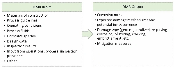
Figure 2. DMR Inputs and Outputs
2.2 Ethane Cracker Process Overview
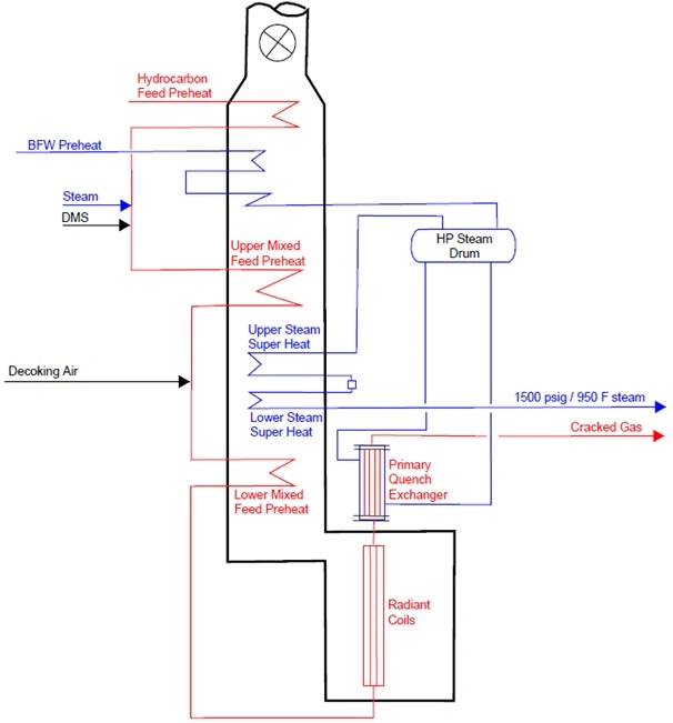
Ethane pyrolysis furnaces produce ethylene and other byproducts by the thermal cracking of ethane rich hydrocarbons in a mixture of steam and hydrocarbon. There are several pyrolysis furnace designs available in industry depending on the specific feedstock and desired products but most have a configuration similar to that shown in Figure 3. Ethane rich hydrocarbon feed entering the convection section is mixed with dilution steam, injected with dimethyl sulfide (DMS), and preheated prior to entering the radiant tubes where the cracking reactions take place. The cracked gas leaving the radiant tubes is rapidly quenched in the Primary Quench Exchangers (PQE) to stop the reaction in order to obtain the desired products. The heat generated by the pyrolysis furnace is also used to produce high pressure steam in the convection section.
The cracking reactions are endothermic and take place at high operating temperatures (1400-1600°F / 760-870°C) with tube metal temperatures reaching 2100°F / 1150°C due to coke buildup. The dilution steam added to the hydrocarbon feed serves to improve the ethylene selectivity and reduce the coking potential. The DMS is used to inhibit coke formation and control the production of CO by passivating the Radiant coils and prevent rapid coking. Coke does build up over time and reduces heat transfer and increases the pressure drop across the tubes requiring the coils to be regularly decoked. Decoking is started with steam at about 1470°F / 800°C and continued with a steam-air mixture up to about 2010°F / 1100°C.
| Process | TMT (°F/°C) | Metallurgy |
|---|---|---|
| Convection Coils | ||
| Hydrocarbon Feed Preheat | 555 / 290 | Carbon Steel |
| BFW Preheat | 560 / 293 | Carbon Steel |
| Upper Mixed Feed Preheat | 900 / 482 | 1.25Cr-0.5Mo |
| Upper Steam Superheat | 950 / 510 | 1.25Cr-0.5Mo or 2.25Cr-1Mo |
| Lower Steam Superheat | 1100 / 593 | 2.25Cr-1Mo, 304H, and 347H |
| Lower Mixed Feed Preheat | 1600 / 870 | 304H and Alloy 800 HT |
| Crossovers and Radiant Coils | ||
| Cross Overs | 1350 / 732 | 304H or 347H |
| Inlet Manifold | 1350 / 732 | 304H or 347H |
| Cold Pass | 1750 / 955 | 25Cr-35Ni |
| Hot Pass | 2010 / 1100 | 35Cr-45Ni |
| Transfer Line and Primary Quench Exchanger (PQE) | ||
| Exit Wye / Transfer Line | 1650 / 900 | Alloy 800 HT or HP Low C(26Cr-35Ni) |
| PQE Tube Side | Alloy 800 inlet nozzle, 1.25Cr-0.5Mo tube | |
| PQE Shell Side | Carbon Steel | |
| PQE Outlet Piping | 2.25Cr-0.5Mo | |
Figure 3. Schematic of a Typical Ethane Pyrolysis Furnace
2.3 Damage Mechanisms in Ethane Crackers
Ethane crackers are susceptible to a number of different damage mechanisms including those that result in the degradation of material properties and those that result in a loss of wall thickness (thinning). A detailed listing of the expected damage mechanisms and damage potentials for each component associated with the Ethane cracker is provided in Table 1. The potential damage mechanisms include the following.
2.3.1Convection Coils (BFW and Steam Superheat)
The boiler feed water (BFW) Preheat coils produce 640 psig superheated steam and Steam Superheat coils produce 1500 psig superheated steam by recovering waste heat from the flue gases in the convection section. Corrosion rates in the BFW Preheat coils are dependent on the quality of the BFW and are typically low (< 1 mpy) unless there are issues with the BFW treatment. Poor BFW quality can introduce a number of damage concerns including general and pitting type corrosion (due to the presence of acid gases), under deposit corrosion, and fouling.
Corrosion and damage protection in the high pressure Steam Superheat coils is maintained by ensuring the presence of a thin protective magnetite scale (Fe3O4). Critical factors that need to be managed include the concentration of dissolved gas (oxygen and/or carbon dioxide), pH, hardness, and the specific BFW treatment system. Poor water chemistry can result in caustic gouging, caustic stress corrosion cracking, scaling, blockage, and steam blanketing which can lead to short term overheat and stress-rupture. In addition, poorly adhering scales and high velocity can result in erosion and erosion corrosion problems.
The upper and lower high pressure Steam Superheat coils have skin temperatures up to 950°F /510°C and 1100°F / 593°C which is above the creep threshold for the typical materials of construction (See Figure 3). Therefore they will accumulate creep over time and are subject to creep-stress rupture as the coils age. Typical coil life is > 20 years. The use of mixed materials (2.25Cr-1Mo ferritic steel and 304H and 347H austenitic stainless steel) can also cause concerns for dissimilar metal weld cracking (DMW) at the high operating temperatures. Additionally, austenitic stainless steel 304H and 347H will develop a sigma phase over time. Sigma is a hard, brittle magnetic phase containing approximately 50% chromium. It results in brittleness and loss of impact strength, which is most apparent at cooler temperatures experienced during shutdowns. The brittleness due to sigma phase formation tends to disappear when the metal is heated above 260°C (500°F) and reappears on cooling below this temperature. Consequently, the likelihood of an on-stream failure due to embrittlement is low, but failures can occur during cool down or during maintenance activities if high stresses or shock loads are introduced. Presence of a sigma phase also increases the susceptibility to intergranular corrosion. Although the individual potentials for creep, DMW cracking, and sigma phase embrittlement are low, a combination of these damage mechanisms can cause medium or high potential for a loss of mechanical properties over time and lead to cracking damage.
2.3.2 Convection Coils (Hydrocarbon Feed and Mixed Feed Preheat)
The Hydrocarbon Feed Preheat coils operate at low temperatures and contain dry hydrocarbon (typically a mixture of ethane and propane) so there are no internal corrosion or other damage concerns. Since low sulfur fuel is used for the furnace, the potential for flue gas dew point corrosion on the tube OD is also low.
The Upper Mixed Feed Preheat coils are typically constructed of 1.25Cr-0.5Mo material and have skin temperatures up to 900°F / 482°C which is above the creep threshold limit (800°F / 427°C) for the material. Therefore the coils will accumulate creep over time and have a low potential for creep-stress rupture. The coils also have a potential for high temperature sulfidic corrosion due to the presence of sulfur species from the use of DMS. The corrosion potential is low due to the low dosage of DMS (in the range of 100 ppm) that is used.
The Lower Mixed Feed Preheat coils are typically constructed of a mix of 304H, 347H, and Alloy 800HT to provide resistance to high temperature damage mechanisms. Skin temperatures can reach 900°F / 482°C at the coil inlet and 1600°F / 870°C at the outlet. The potential for creep is high, particularly for the coil outlets. In addition, the 304H and 347H materials have a high susceptibility to sigma phase embrittlement. The high skin temperatures also induce coking which promotes carburization.
Carburization results in carbon being absorbed in the steel to form metal carbides. Carburization damage results in a loss of high temperature creep ductility and loss of toughness when the heater is cooled down to ambient conditions. The corrosion resistance is also decreased due to the change in microstructure. Decoking cycles accelerate the carburization process and also introduce concerns with thermal fatigue due to the thermal cycles. Thermal cycles can also be induced from the expansion and contraction experienced from furnace trips and startups/shutdowns. The combination of these damage mechanisms makes the coil butt welds and attachment welds at high risk for cracking. To compound the problem, the change in microstructure results in a loss of weldability. Therefore tube life is typically limited by weld cracking and ability to carry out weld repairs.
Tube replacements driven by the thinning damage mechanisms which include erosion (due to decoking), metal dusting, and external oxidation are less prevalent. Metal dusting is a severe form of carburization that occurs when the carbon diffusion rate is uncontrolled. It results in the formation of a fine powder of iron carbide or pure metal and carbon dust causing rapid metal loss. Once initiated it is difficult to control. Oxidation occurs when oxygen in the combustion air reacts with iron in the steel to form metal oxides. Oxidation corrosion rates depend on the material of construction and TMT and should be less than 5 mpy for the typical combination of materials and TMT.
Other external damage concerns stem from sulfur present in the fuel gas. Although low sulfur fuel is used for the Ethane pyrolysis furnaces, presence of low levels of sulfur species in the fuel can result in the development of iron sulfide scale (over an extended period of time) and lead to concerns for polythionic acid stress corrosion cracking (PTASCC) on the tube OD. PTASCC typically occurs in sensitized austenitic stainless steel materials during downtime when polythionic acids form from the presence of sulfide scale, air, and moisture. Sensitization results in the precipitation of chromium carbides at the grain boundaries and increases the potential for intergranular corrosion. PTASCC has not been a concern for the tube ID's of Ethane crackers. PASCC less likely to occur in the 347H chemically stabilized stainless steel materials since they are less prone to sensitization; the 304H SS and Alloy 800HT coils are the main concern.
2.3.3 Crossovers and Radiant Section Inlet Manifold
Most designs use 304H or 347H SS for the Crossover and Inlet Manifold piping to the Radiant coils. High process temperatures of 1230°F / 666°C are experienced in Crossovers and Inlet Manifold. The corrosion and damage concerns are similar to those experienced in the Lower Mixed Feed Preheat coils and include creep, carburization, sigma phase embrittlement, thermal fatigue, and erosion. Due to the high temperatures experienced and combination of damage mechanisms that result in a loss of mechanical properties, Crossover and Inlet Manifold welds have a high potential for cracking. Poorly supported pipe (e.g. due to improper spring hanger calibration, damaged supports, or poor design) increase the stresses and result in even higher damage potentials. Repair welding becomes increasingly difficult over time due to the change in microstructure. Therefore the useful tube life is often limited by the ability to perform weld repairs.
2.3.4 Radiant Coils
Process temperature is increased in the Radiant coils from about 1230°F / 666°C to 1580°F / 860°C. Most of the Radiant coils include a cold pass and hot pass connected by welds at the return bends. Current designs use centrifugally cast tubes with 25Cr-35Ni for the cold pass and 35Cr-45Ni for the hot pass. The alloys have an austenitic microstructure, high mechanical strength, and are very resistant to high temperature damage. Several different alloy grades are available. The different alloys employ various additions of carbide forming elements such as niobium, titanium, tungsten and molybdenum to improve the creep strength in the high temperature range. The tungsten, titanium, and niobium alloying elements also improve resistance to carburization.
Skin temperatures are in the order of 1750°F/ 955°C for the cold pass and 2010°F / 1100°C for the hot pass. Due to the very high temperatures experienced and frequency of decoking cycles (about every 20 to 60 days), the radiant tubes can be subject to high potentials for creep, carburization, and thermal fatigue. The welds are particularly sensitive to cracking due to the change in microstructure (which reduces the strength) and higher residual stresses that are present. The precipitation of a sigma phase reduces creep ductility during operation as well as fracture toughness when the tubes are cooled below 500°F / 260°C. In addition, solids (spalled coke) present from the frequent decoking cycles result in concern for erosion damage, particularly in areas of turbulence such as elbows and reductions.
The combination of creep and carburization are the most prevalent damage mechanisms that limit Radiant tube life. The use of 25Cr/35Ni and 35Cr/45Ni alloys which readily form chromium oxide scale and DMS injection which promotes the formation of iron sulfide scales, provide carburization resistance. However mechanical damage experienced during the decoking cycles and presence of locally hot areas from the burning of coke deposits cause the protective layers to be disrupted, forming gaps in the scale where the metal base can be exposed to carburization. Cracks formed in the chromium oxide layer as a result of creep or fatigue accelerate the carburization process. Once the carburization process is thus initiated, it is difficult to control and is the primary reason for premature Radiant tube failures.
Industry experience shows the Radiant tubes experience severe levels of carburization and creep damage and generally do not last up to their estimated design life. Therefore, special attention is required to improve their reliability. An IOW program can be used to define the operating limits based on the particular process conditions and materials of construction in order to monitor key process parameters that can influence tube life; a discussion of IOW's is provided later in this report. Additionally, mitigation measures including metallurgy upgrades to provide high temperature damage resistance, use of anti-foulants to resist the formation of coking, use of catalytic or diffusion coatings to reduce carburization, and design changes to reduce tube fouling and improve run lengths have been implemented by many operating units. A discussion of the mitigation measures is outside the scope of this paper.
2.3.5 Radiant Coil Exit Wye / Transfer Line
The pyrolysis furnace effluent leaves the radiant tubes at process temperatures of around 1580°F / 860°C and the Radiant coil Exit Wye / Transfer Line TMT's can reach 1650°F / 900°C at end of run conditions. Materials of construction are typically high chromium nickel alloys (such as Alloy 800 HT or HP Low C) to provide high temperature damage resistance. The main damage concerns are due to creep, carburization, thermal fatigue, sigma phase embrittlement (particularly for HP Low C materials), and erosion due to the high skin temperatures and exposure to the decoking process. As previously discussed, welds are particularly vulnerable to cracking.
2.3.6 Primary Quench Exchangers
The cracked gas is rapidly quenched from 1580°F / 860°C to 830°F / 445°C on the tube side of the PQE's by generating high pressure steam on the shell side. There are several different designs and materials that are currently used for PQE's to provide the rapid quench required while mitigating against the expected damage mechanisms. The designs vary from tube in tube to shell and tube exchangers. The PQE inner tubes and bundles are typically constructed of 1.25Cr-0.5Mo and the shells are usually carbon steel. The material selection for the inlet cone/channel may vary from Alloy 800 HT (tube in tube design) to carbon steel or 1.25Cr-0.5Mo refractory lined (shell and tube design).
- PQE inlet channels/cones constructed of Alloy 800 HT are susceptible to damage mechanisms that are similar to the transfer line (creep, carburization, thermal fatigue, and erosion). Refractory lined channels are susceptible to refractory damage which can result in high skin temperatures inducing creep and high temperature sulfidic corrosion (due to the use of DMS) to the base metal.
- PQE tubesheets (where present depending on the design) are susceptible to thermal fatigue due to the high delta T experienced from the rapid quenching of the cracked gas; seal welds have a high potential for cracking. For tube in tube exchangers, dissimilar metal weld (DMW) cracking at the inlet cone to inner tube joint weld is a concern.
- PQE tubes are subject to fouling and plugging from coke and poly oils as well as erosion corrosion from coke fines, particularly during decoking operations on the process side. Boiler water corrosion is a concern on the shell side. Tube side plugging results in a loss of heat transfer and can lead to short term overheat. The tubes and outlet channels can also experience high temperature sulfidation in the presence of hydrogen (due to the DMS injection). The API 939C Couper Gorman curves are typically used to calculate sulfidic corrosion rates in the presence of hydrogen.
- PQE outlet piping is susceptible to erosion corrosion and very high rates of wall loss (upwards of 40 mpy) have been reported in some cases. High temperature sulfidation in the presence of hydrogen is also a potential damage mechanism but low corrosion rates are expected from sulfidation.
3. RBI AND INSPECTION PLANS
The results of the DMR are used to calculate relative risk and generate inspection plans. Risk calculations can be performed using various methodologies ranging from qualitative to fully quantitative. Due to the availability of, and industry experience with, commercial software that facilitates the RBI implementation process, a semi-quantitative approach using RBI software is often used. This provides a practical approach to developing initial inspection plans based on relative risk as well as facilitating the evergreen process.
A key factor in developing the inspection plan is to ensure that inspection tasks look for damage mechanisms identified by the DMR. Table 1 and Table 2 highlight the importance of understanding how the design, process, and operating conditions affect the materials of construction for each component in order to accurately identify the expected damage mechanisms and type of damage expected so that inspections can be carried out at the optimum locations and using the correct inspection technique to look for the expected damage. Incorrect identification of damage mechanisms and their potentials can result in unidentified or increased risk to the unit while overstating the damage potentials can result in increased inspection efforts without reducing risk, or worse - diverting resources from areas requiring attention.
To illustrate the process of identifying inspection methods, we can take the information in Table 2 as an example. Table 2 links the expected damage mechanisms with the type of damage expected (e.g. thinning, pitting, cracking, loss of material properties) and inspection method required to detect damage for the key components in the Ethane crackers. As an example, the Lower Mixed Feed Preheat coil in Table 2 is susceptible to several high temperature damage mechanisms including Creep (High), Carburization (Medium), Sigma Phase (High), and Oxidation (Low). These damage mechanisms can result in a loss of material properties manifesting as bulging, sagging, and cracking. Therefore some of the inspection methods identified to look for this type of damage include Visual inspections of tubes and supports to look for obvious signs of damage, Dimensional inspection (e.g. via strapping, laser profilometry) to identify bulging or changes in dimensions, and PT or UTSW to identify cracking.
The inspection frequency and extent of inspection are derived from the overall risk from the risk calculation and are outside the scope of this paper. The frequency of inspection required to look for damage from each of the different damage mechanisms can vary significantly depending on the damage potential and risk ranking. For example, cracking inspections for the Lower Mixed Feed coils may be required every 2-3 years due to the high potential for cracking but inspection intervals for thinning may be much less frequent if experience shows the potential for thinning (e.g. due to erosion) has not been a concern.
4. INTEGRITY OPERATING WINDOWS
The DMR and RBI efforts provide the following information:
- Corrosion Rates and type of damage expected
- Damage Mechanisms and potentials
- Type of Damage Expected (e.g. thinning, pitting, cracking, etc.)
- Prioritized risk for each component
- Inspection Plans - method, frequency, location
A good starting point in determining the process parameters that should be monitored for the IOW program is to review each damage mechanism listed in the "Damage Mechanisms" column in Table 1 and identify the impact process deviations can have on the damage potential. Once the process parameter to monitor has been identified, industry standards, best practices, design values, and corrosion models can be used to identify the values for the IOW limits. When setting the IOW limits, it is important to consider what is an "acceptable" degradation rate for the affected equipment, how quickly personnel are able to respond if the IOW limit is exceeded, and the time required to bring the process parameter within acceptable limits once the response is taken. The actual limits that are set will be based on the risk tolerance of the company combined with the practical operation of the plant. For example, setting a temperature limit for creep that is too low will have operators constantly reacting to alarms and leave little room to operate. Conversely, if the limit is too high the equipment may sustain rapid degradation leading to increased risk and significantly reduced remaining life.
Table 3 illustrates how monitoring of process parameters are linked with potential damage mechanisms that affect the various components associated with the pyrolysis furnace. A discussion of a few of the Ethane Cracker process parameters to monitor and the rationale for monitoring is provided below. The below listing is not intended to be all inclusive, but rather to be used as a starting point for developing IOW process parameters to monitor.
| Hydrocarbon Feed Composition | Olefins in the recycle ethane (e.g. ethylene) can increase the coking tendency which can increase the potential for a variety of high temperature damage mechanisms as discussed above. Monitor the olefins in the feed to the pyrolysis furnace and set operational limits. |
| Hydrocarbon Feed rate | A complete loss of or significant reduction in the hydrocarbon feed can cause short term overheat if the furnace is not promptly shut down since the furnace will still be firing while endothermic cracking reactions will no longer be taking place. |
| Steam Injection rate | Dilution steam reduces the coking tendency. The steam to hydrocarbon ratio is based on process requirements and economics. Monitor the steam injection rate to ensure the correct steam to hydrocarbon ratio required to minimize fouling is achieved. A loss of steam can cause excessive fouling and lead to short term overheat. |
| DMS Injection Rate | DMS is used to passivate the Radiant coils in order to mitigate against carburization. A low and high limit are both required for the DMS injection rate since too little DMS causes inadequate passivation of the radiant tubes resulting in increased carburization rates and a decrease in tube life. Too high of a DMS injection rate can cause high temperature sulfidic corrosion to carbon steel and low alloy steel heater tubes, heater outlet piping, and quench exchangers. It can also cause an increase in neutralizer demand for the Quench Tower as well as increased demands in the caustic treatment area. |
| Process Temperature | Process temperature is an important parameter in determining and managing the coking potential. A reduction in the coking rate, and therefore the decoking frequency helps reduce several of the high temperature damage mechanisms including carburization, creep, and thermal fatigue and helps increase the radiant tube life. Monitor the process temperature in several locations in the furnace including radiant coil inlet and outlet. |
| Tube Metal Temperature | Excessively high skin temperatures can lead to damage due to creep, carburization, and higher rates of coking. Higher coking rates decrease heat transfer, which leads to even higher skin temperatures and shorter runs. Monitor tube metal temperatures online via skin TI's at the Radiant coil inlet (indicates whether incipient hydrocarbon cracking is a concern in the convection section) and at the Radiant coil outlet (indicates the coking severity and whether decoking is required). In addition, periodically use IR Thermography and Pyrometry to monitor for hot spots. Visually look for flame instabilities and impingement once or twice per shift to ensure no hot spots that can cause localized overheating. |
| Pressure Drop Across Radiant Tubes | Pressure drop across the radiant tubes is an indicator of when decoking is required (outlet to inlet pressure ratio of <0.9 is typically specified to indicate decoking). Excessive pressure drop across the tubes indicates plugging and coking problems which can cause an increase in tube metal temperature (due to endothermic nature of the process) leading to increased creep potential and short term overheat. |
| PQE Outlet Temperature | PQE tube side outlet temperature is an indicator of whether decoking is required due to fouling and plugging of the PQE tube side. |
| Pressure Drop Across PQE Tubes | A high pressure drop across the PQE tubes indicates plugging problems from coke fines and/or poly oils. Plugging results in short-term overheat of the tubes and high temperature damage mechanisms in upstream components. |
| Number of Furnace Trips | Increased furnace trips resulting in increased thermal fatigue potential and decrease the furnace tube life. Record the number of occurrences of furnace trips to determine if the inspection frequency for thermal fatigue needs updating; The information can also be used for fitness for service evaluations. |
| Spring Hanger Calibration | Improper spring hanger calibration can cause increased stresses on the tubes leading to increased damage from creep and thermal fatigue. |
| BFW Quality | BFW quality affects multiple aspects of corrosion and damage in BFW and steam service. Corrosion and damage protection is maintained by ensuring the presence of a thin protective magnetite scale (Fe3O4). Poor water chemistry can result in caustic gouging, caustic stress corrosion cracking, scaling, blockage, and steam blanketing which can lead to short term overheat and stress-rupture. In addition, poorly adhering scales and high velocity can result in erosion and erosion corrosion problems. Critical factors that need to be monitored in BFW include pH, Conductivity, Silica, Total Iron, Total Hardness, Oxygen, Chloride, Sulfate, Silica, Sodium + Potassium. |
| H2S in the Fuel Gas | H2S in the flue gas can form sulfuric and/or sulfurous acids which can condense on the tube OD (during operation or downtime) and cause corrosion problems in the cooler sections in the convection section. It can also lead to external sulfide scaling over time and introduce concerns for PTASCC of austenitic stainless steel components in the hotter sections of the furnace. The H2S content in fuel gas should be kept as low as possible. |
SUMMARY
This paper outlines a methodology for using RBI, DMR, and IOWs to manage the reliability of ethane crackers based on API standards. A well implemented and managed reliability program incorporating these processes can identify potential damage mechanisms, optimize maintenance and inspection, reduce risks and improve the governance in managing Ethane Crackers. The key elements of the program include:
- An understanding of the damage mechanisms through a DMR to ensure inspections focus on looking for the right type of damage.
- An RBI program to prioritize risk and ensure components are inspected using the right inspection technique and at the right frequency.
- An IOW program to provide real time notification of process deviations in order to avoid premature damage that can shorten equipment life.
Table (1): Damage Mechanisms in Ethane Crackers
| Process | Process Temp (°F/°C) | TMT (°F/°C) | Metallurgy | Damage Mechanisms | Corrosion Rate (mpy) Note (1) |
|---|---|---|---|---|---|
| Hydrocarbon Feed Preheat | In: 140 / 60 Out: 430 / 220 | 555 / 290 | Carbon Steel |
| 0.5 |
| BFW Preheat | In: 284 / 140 Out: 420 / 215 | 560 / 293 | Carbon Steel |
| 1 |
| Upper Mixed Feed Preheat | In: 500 / 260 Out: 760 / 405 | 900 / 482 | 1.25Cr-0.5Mo |
| 2 |
| Upper Steam Superheat | In: 620/327 Out: 775/413 | 950 / 510 | 1.25Cr-0.5Mo 2.25Cr-1Mo |
| 1 |
| Lower Steam Superheat | In: 740 / 395 Out: 950 / 510 | 1100 / 593 | 2.25Cr-1Mo 304H 347H |
| 1 |
| Lower Mixed Feed Preheat | In: 630 / 332 Out: 1230 / 665 | 1600 / 870 | 304H and Alloy 800 HT |
| 5 (Localized) |
| Cross Overs | 1230 / 665 | 304H or 347H |
| 3 (Localized) | |
| Inlet Manifold | 1230 / 665 | 304H or 347H |
| 3 (Localized) | |
| Cold Pass | In: 1230 / 665 | 1750 / 955 | 25Cr-35Ni HP Micro |
| 3 (Localized) |
| Hot Pass | Out: 1580 / 860 | 2010 / 1100 | 35Cr-45Ni |
| 3 (Localized) |
| Exit Wye / Transfer line | 1580 / 860 | 1650 / 900 | Alloy 800 HT or HP Low C (26Cr-35Ni) |
| 3 (Localized) |
| PQE Tube Side | In: 1580 / 860 | Alloy 800 inlet nozzle 1.25Cr-0.5Mo tube |
| 5 | |
| PQE Shell Side | In: 620 / 325 | Carbon Steel |
| 1 | |
| PQE Outlet Piping | 830 / 445 | 2.25Cr-0.5Mo |
| > 10 (Localized) | |
| Note 1: The corrosion rates in this table are for illustration purposes and are derived from experience with Ethane Crackers in several different units. Actual corrosion rates for a particular unit will be based on the design, materials of construction, process information, and operating conditions, for the particular unit and should be validated using field data. | |||||
Table (2): Inspection Methods Based on DMR Results
| Process | Damage Mechanisms Note (1) | Type of Damage Expected | Inspection Method Note (2) | ||
|---|---|---|---|---|---|
| Hydrocarbon Feed Preheat |
|
|
| ||
| BFW Preheat |
|
|
| ||
| Upper Mixed Feed Preheat |
|
|
| ||
| Upper Steam Superheat |
|
|
| ||
| Lower Steam Superheat |
|
|
| ||
| Lower Mixed Feed Preheat |
|
|
| ||
| Cross Overs |
|
|
| ||
| Inlet Manifold |
|
|
| ||
| Cold Pass |
|
|
| ||
| Hot Pass |
|
|
| ||
| Exit Wye / Transfer line |
|
|
| ||
| PQE Tube Side |
|
|
| ||
| PQE Shell Side |
|
|
| ||
| PQE Outlet Piping |
|
|
| ||
| Note 1: The damage potentials in this table are for illustration purposes and are derived from experience with Ethane Crackers in several different units. Actual potentials for a particular unit will be based on the design, materials of construction, process information, and operating conditions, for the particular unit and should be validated using inspection data. Note 2: These are examples of some of inspections methods used to look for the expected damage. Various other NDT methods are available in industry and this table is not meant to be a comprehensive list of all available inspection techniques. | |||||
Table (3): Example of IOW Process Parameters and the Link with Damge Mechanisms
| IOW No. | IOW Description | Affected Areas | Process Variable to Monitor | Relevant Damage Concerns | IOW Limits | Monitoring Method | Monitoring Frequency |
|---|---|---|---|---|---|---|---|
| 1. | Hydrocarbon Feed Composition | Ethane Cracker tubes, transfer line, PQE's, and downstream piping. | Olefin content in hydrocarbon feed | Coking in the heater tubes leading to an increase in high temperature damage mechanisms (listed in Table 1) and thermal fatigue. | Consult Process Engineering | Consult Process Engineering | Consult Process Engineering |
| 2. | Hydrocarbon Feed rate | Ethane Cracker tubes, transfer line, PQE's, and downstream piping. | Hydrocarbon flow rate |
| Consult Process Engineering | Online flow rate monitoring | Online (Continuous) |
| 3. | Steam Injection rate | Ethane Cracker tubes, transfer line, PQE's, and downstream piping. | Dilution steam flow rate |
| Consult Process Engineering | Online flow rate monitoring | Online (Continuous) |
| 4. | DMS Injection Rate | Ethane Cracker tubes, transfer line, PQE's, and downstream piping. | DMS injection rate | Coking in the heater tubes leading to an increase in high temperature damage mechanisms (listed in Table 1) and thermal fatigue. | Consult Process Engineering | Online flow rate monitoring | Online (Continuous) |
| 5. | Process Temperature | Ethane Cracker tubes, transfer line, PQE's, and downstream piping. | Process Temperature | Coking in the heater tubes leading to an increase in high temperature damage mechanisms (listed in Table 1) and thermal fatigue. | Consult Process Engineering | Online temperature monitoring | Online (Continuous) |
| 6. | Tube Metal Temperature | Ethane Cracker tubes, transfer line, PQE's, and downstream piping. | Tube Metal Temperature | Coking in the heater tubes leading to an increase in high temperature damage mechanisms (listed in Table 1) and thermal fatigue. | Based on Process and Reliability Engineering Requirements | Online temperature monitoring | Online (Continuous) |
| 7. | PQE Outlet Temperature | Radiant coils, transfer line, and PQE's (tube side). | PQE outlet temperature | Coking and plugging of PQE's indicating decoking is required. Failure to decoke increases potential for high temperature damage mechanisms in the piping components upstream of the PQE's. | Consult Process Engineering | Online temperature monitoring | Online (Continuous) |
| 8. | Pressure Drop across the Radiant Tubes | Radiant coils, transfer line, and PQE's (tube side). | Pressure drop across Radiant Tubes | Coking and plugging of the radiant coils indicating decoking is required. Failure to decoke increases potential for high temperature damage mechanisms and short term overheat. | Consult Process Engineering | Online pressure monitoring | Online (Continuous) |
| 9. | Pressure Drop across PQE Tubes | Radiant coils, transfer line, and PQE's (tube side). | Pressure drop across PQE tubes | Coking and plugging of PQE's indicating decoking is required. Failure to decoke increases potential for high temperature damage mechanisms in the piping components upstream of the PQE's. | Consult Process Engineering | Online pressure monitoring | Online (Continuous) |
| 10. | Number of Furnace Trips | Ethane Cracker tubes | Number of Furnace Trips | Thermal Fatigue | Any. Record the number of furnace trips for future engineering evaluations. | Record Number of Furnace Trips | Record Number of Furnace Trips |
| 11. | Spring Hanger Calibration | Ethane Cracker tubes | Travel Limits | Creep, Thermal Fatigue | Based on design | Monitor Travel Limits on the Spring Cans | Six monthly |
| 12. | BFW Quality | Steam Coils and PQE Shell side | Multiple (See Comments) | Boiler Water corrosion, fouling, erosion corrosion, fouling, caustic corrosion, caustic SCC, steam blanketing, short term overheat. | Per water treatment vendor recommendations | Per water treatment vendor recommendations | Per water treatment vendor recommendations |
| 13. | H2S in the Fuel Gas | Coils in the convection section | H2S in the Fuel Gas |
| As low as possible | Set a limit for sulfur content in purchased and recycle fuel gas and test periodically | Based on expected variability of sulfur levels in the fuel source. |
REFERENCES
- API RP 581, Risk-Based Inspection Methodology, Third Edition, April 2016. API Publishing Services, 1220 L Street, N. W., Washington, D. C. 20005.
- API RP 580, Risk Based Inspection, Third Edition, February 2016. API Publishing Services, 1220 L Street, N. W., Washington, D. C. 20005.
- API RP 571, Second Edition, April 2011, "Damage Mechanisms Affecting Fixed Equipment in the Refining Industry", API Publishing Services 1220 L Street. N.W. Washington DC 20005.
- API RP 584, First Edition, May 2014, "Integrity Operating Windows", API Publishing Services, 1220 L Street, N. W., Washington, D. C. 20005.
- J. Robinson, 2014, "Avoiding Waterside Corrosion Problems in Ethylene Plant Steam Systems". GE Power & Water Technical Paper GE Water and Process Technologies, Trevose, PA, USA.
- H.J. Grabke, "Carburization A High Temperature Corrosion Phenomenon", (1998, Materials Technology Institute for the Chemical Process Industries, Inc.). MTI Publication No. 52.
- C. M. Schilmoller, "HP Modified furnace tubes for steam reformers and steam crackers". Nickel Development Institute. NIDI Technical Series No 10 058.
- R.C. Yin, A.H. Al-shawaf, B.Y. Al-yami, A.A. Al-Ahmari, "Failure Experiences of Ethylene Cracking Tubes". Corrosion 2009 NACE Paper 09159.
- Istvan Kucora, Ljiljana Radovanovic, "Pyrolysis Furnace Tube Damaging and Inspection". ACETA Tehnica Corviniensis - Bulletin of Engineering Fascicule 3 [July-September] Tome VII [2014]. ISSN: 2016-3809.
Publication Inquiry