
INTRODUCTION
Hydrogen plants are subject to severe operating conditions that can induce accelerated aging of piping and fixed equipment. Damage mechanisms associated with the aging process include corrosion, creep, high temperature hydrogen attack (HTHA), thermal fatigue, stress relaxation cracking, sigma phase embrittlement, oxidation, and carburization, among others. Factors such as cyclic service, high operating temperatures, unexpected shutdowns, and operational breaches (outside normally expected or design conditions) can induce or enhance the occurrence of the damage mechanisms and accelerate the aging process; therefore, special attention is needed to avoid unexpected catastrophic failures.
Risk Based Inspection (RBI) methodologies incorporating a damage mechanism review (DMR) can be used to manage the assets in aging plants and reduce the risk of loss of containment by identifying the damage mechanisms that are expected to occur in each piece of fixed equipment and piping, calculating the risk associated with a potential loss of containment, and clearly defining inspection plans based on the RBI assessment results. If inspection results show symptoms of degradation or accelerated aging, fitness for service (FFS) evaluations may be required to ensure the mechanical integrity of the asset.
Since RBI utilizes process conditions essentially as a "snapshot" in time to recommend inspection plans, day-to-day changes in process conditions are not fed back into the risk calculation. A well-designed and implemented integrity operating windows (IOW) program can help bridge the gap by providing real time notification of key process parameters that can accelerate degradation and increase risk.
This article discusses the use of the RBI methodology supplemented by a well-designed IOW program to assess and manage aging in fixed equipment and piping in hydrogen generation units; a similar methodology can be used to manage aging of other process units.
WHAT IS AN AGING PLANT?
The concept of aging plants is not straightforward since it is not just about the time the asset has been in service. The UK Health and Safety Executive (HSE) published guidelines for managing aging plants that describe aging plants as follows:
- Aging is the effect whereby a component suffers some form of material deterioration and damage.
- Aging is not about how old your equipment is; it is about its condition and how that is changing over time.
- Just because equipment is old does not necessarily mean it is significantly deteriorating and damaged.
Due to the nature of the process, some plants are more susceptible to the aging effect than others. In these cases it is necessary to put the best strategy in place to reduce rapid degradation and the risk of failures. This article is focused on providing a useful methodology to manage aging assets which operate under critical conditions and subject to rapid deterioration.
INTEGRATING DMR, RBI, AND IOWS TO MANAGE AGING PLANT RELIABILITY
RBI methodology is not new to the refining and petrochemical industries and has been around since the 1990's, with the first edition of API 581 published in 1996. It is used to prioritize and manage the efforts of an inspection program to ensure inspection is carried out at optimum intervals, at the right locations, and using the right technique to find expected damage. However, simply having an RBI program in place does not in itself reduce risks in a plant or help manage costs.
Significant value can best be realized when the program is well-implemented using a systematic, comprehensive, and thorough approach in line with the best practices of a robust safety culture. The use of a damage mechanism review (DMR) to identify the key damage mechanisms assets are susceptible to, the type of damage that is expected, and the damage rate, along with a well-implemented IOW program to provide real time monitoring of process conditions in order to detect increased risk, can significantly improve the management of assets. The integration of DMR, RBI, and IOWs is illustrated in Figure 1 which illustrates the overall RBI process.
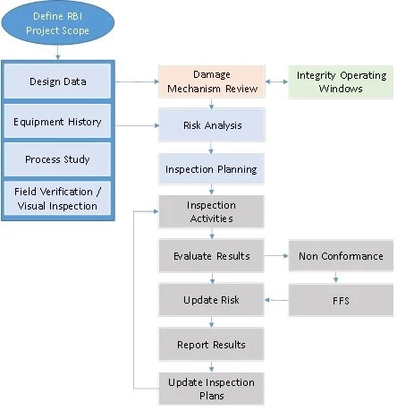
Figure 1. Integration of RBI, DMR, and IOWs
To illustrate the process and benefits of integrating DMR, RBI, and IOWs to manage assets in aging plants, the section below provides an example of using the integrated methodology to manage an aging hydrogen generation unit.
Damage Mechanisms in Aging Hydrogen Plants
Hydrogen generation units produce high purity (98%+) hydrogen by steam reforming light hydrocarbons, such as natural gas, sweet LPG, or naphtha at high temperatures. The steam hydrocarbon reforming reaction is endothermic and takes place at high operating temperatures (1450-1580°F), with tube metal temperatures reaching 1700°F in the firebox. Significant heat is required to produce the desired products. Reformer assets operate at very high temperature and are also subject to thermal stresses, high flow velocities, fouling, and corrosive byproducts.
At these conditions, materials of construction can be subject to a variety of damage mechanisms which can cause rapid degradation and accelerate aging. The damage mechanisms include corrosion, creep, high temperature hydrogen attack (HTHA), thermal fatigue, stress relaxation cracking, sigma phase embrittlement, oxidation, and carburization, among others. Factors such as cyclic service, high operating temperatures, unexpected shutdowns, and operational breaches (outside normally expected or design conditions) can induce or enhance the occurrence of the damage mechanisms and accelerate the aging process. Therefore, special attention is needed to avoid unexpected catastrophic failures.
Damage Mechanisms Review (DMR)
A DMR is a systematic and thorough review of corrosion and other damage mechanisms in the plant and is typically carried out during an RBI implementation and periodically updated. Typical inputs and outputs of a DMR are provided in Figure 2.
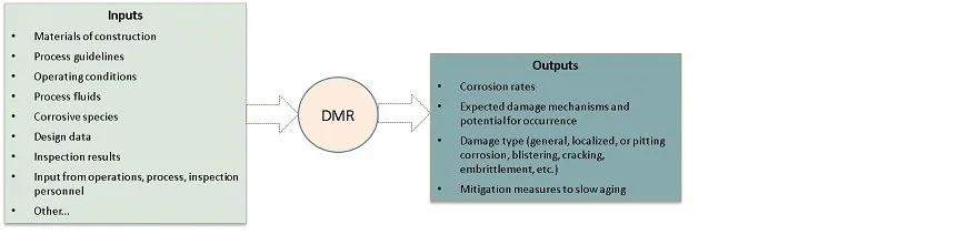
Figure 2. DMR Inputs and Outputs
It is important to note the DMR is not just a "copy and paste" of the damage mechanisms from API 571, as illustrated in Figure 3, but specific to the design, metallurgy, and operating conditions experienced in the process unit being assessed. Attention to detail is critical in achieving a good outcome. Since a vast amount of data is collected during an RBI implementation and updated during revalidation by a variety of plant personnel, there is significant room for error, even with a robust QA/QC program in place. Therefore, it is important not only to understand where the data is coming from, but also do a "sense check" to see if it makes sense.
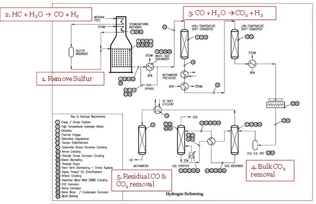
Figure 3. API 571 Damage Mechanisms for a Hydrogen Plant
Errors in the data provided, or incorrect interpretation of the data, can result in a failure to identify applicable damage mechanisms and missed opportunities to look for the damage during inspections. Conversely, identification of damage mechanisms that are not realistic in the unit can result in increased inspection spending without bringing value.
The value in carefully evaluating data can be illustrated by looking at some of the details in Table 1, which provides a summary of the data inputs and results of a DMR for the hydrogen reformer tubes. As shown in Table 1, "Furnace Convection Sec. 2" is constructed of mixed metallurgy (1.25Cr-0.5Mo with bottom 3 passes 304 SS) and it is important to understand where the process data, particularly temperature, comes from when determining whether the tubes are susceptible to creep damage. For example, does the temperature information represent inlet or outlet conditions? Is it skin or process temperature? Also, how was the temperature data collected and was it measured or was it calculated using process simulations? If process simulations were used, were the assumptions made in the simulation software realistic based on actual conditions in the unit (e.g., was the correct level of fouling used to calculate a fouling factor).
| Equipment | Process Fluid | Given Temp (F) Note(1) | Metallurgy | Damage Mechanisms | Corrosion Rate (mpy) | Comments |
|---|---|---|---|---|---|---|
| Furnace Convection Sec. 1 | Hydrocarbon Feed (CH4, C2H6, H2) | 750 | 1.25Cr-0.5Mo |
| 5 | Obtain H2PP to ensure conditions are below the Nelson curve. Verify Cr content of tubes. Use the 1.25 Cr or 1.0 Cr Nelson curve based on the actual chromium content. |
| Furnace Convection Sec. 2 | Mixed Feed (CH4, C2H6, H2, H2O) | 1000 | 1.25Cr-0.5Mo, Bottom 3 passes 304 SS |
| 3 | Obtain H2PP to ensure conditions are below the Nelson curve. Verify Cr content of tubes. Use the 1.25 Cr or 1.0 Cr Nelson curve based on the actual chromium content. |
| Furnace Inlet Headers and Pigtails | CH4, C2H6, H2, H2O, CO, CO2 | 1050 | 1.25Cr-0.5Mo |
| 3 | Obtain H2PP to ensure conditions are below the Nelson curve. Verify Cr content of tubes. Use the 1.25 Cr or 1.0 Cr Nelson curve based on the actual chromium content. Inlet pigtail connections can experience TF due to steam condensing at top of tubes with liquid water running down the tube and revaporizing if proper insulation is not maintained. Creep damage is also likely to occur since the components operate above the creep threshold for 1.25Cr-0.5Mo steel. |
| Furnace Radiant Section | CH4, C2H6, H2, H2O, CO, CO2 | 1450 (Skin < 1700) | HP Modified (PWHT) |
| 1 | High skin temperatures (TMT), high induced stresses on the tubes (expansion and contraction of the tubes during start-ups and shut downs), dissimilar metallurgy of welds, internal fouling and frequent shutdowns can enhance occurrence of the listed damage mechanisms. |
| Reducer, Outlet Pigtails | CH4, C2H6, H2, H2O, CO, CO2 | 1500 | Alloy 800HT |
| 1 | Reducers and outlet pigtails are subject to high operating temperatures and high induced stresses. |
| Outlet Header | Methane + Hydrogen + Steam + CO + CO2 | 1500 | C-0.5Mo (PWHT), Refractory lined |
| 1 | Refractory Damage could result in hot spots and promote Creep, HTHA, short term overheat, and carbonic acid corrosion. |
| Note 1: This is the temperature information provided by process. It needs to be understood by the corrosion specialist using the information whether it represents inlet or outlet conditions, if it is skin or process temperature, and how the temperature data was collected. | ||||||
Table 1. Damage Mechanisms in the Hydrogen Reformer
RBI and Inspection Plans
The results of the DMR are used to calculate risk and generate the inspection plans. Inspection plans can be developed using different methodologies. However, RBI is currently one of the most commonly used methodologies due to its practical approach to developing optimized inspection plans based on risk and the availability of commercial software that facilitates its implementation and evergreen process.
An illustration of an inspection plan for the hydrogen reformer tubes is provided in Figure 4. The figure highlights the importance of understanding the process and operating conditions in order to accurately identify the expected damage mechanisms and type of damage expected so that inspections can be carried out at the optimum locations, using the correct inspection technique, to look for the expected damage. As previously stated, identifying damage mechanisms that do not apply (e.g., HTHA, creep, carburization, etc.) can result in unnecessary inspections and conversely, failure to identify viable damage mechanisms can result in unidentified increased risk to the unit.
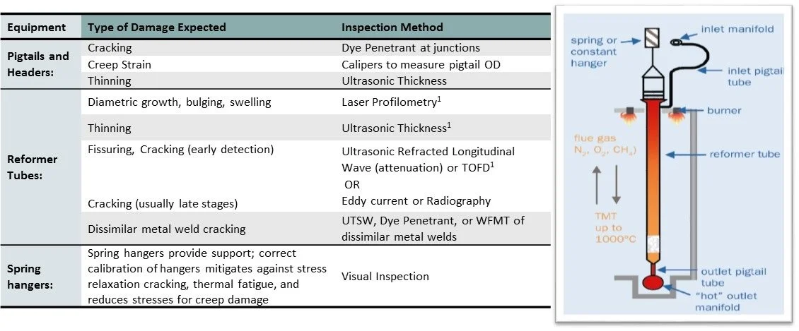
Figure 4. Hydrogen Reformer Inspection Plan
Integrity Operating Windows
The DMR and RBI results provide the following information and may also identify whether a fitness for service evaluation is required for safe operation of the unit.
- Corrosion Rates and type of damage expected
- Damage Mechanisms and potentials
- Prioritized risk for each component
- Inspection Plans - method, frequency, location
This may be sufficient for equipment operating at fairly steady operating conditions, but equipment subject to process fluctuations can benefit from additional real time monitoring via an IOW program to ensure unexpected rapid aging is not occurring. The establishment of an IOW program requires a multidisciplinary team of SME's and may take several months or more to implement. Below are the basic steps to implementing a program.
| Equipment | Process Outlet Temp (°F) | Metallurgy | Damage Mechanism | IOW Process Parameter to Monitor | Standard IOW Limit (Low) | Standard IOW Limit (High) | Comments |
|---|---|---|---|---|---|---|---|
| Furnace Convection Sec. 1 | 700 | 1.25Cr-0.5Mo |
| BFW Quality | Note(1) | Note(1) | BFW quality affects multiple aspects of corrosion anddamage including inducing erosion and fouling. Excessive fouling can lead to short term overheat. |
| Skin Temperature | - | 850°F Note(2) | High skin temperatures can induce creep. | ||||
| Furnace Convection Sec. 2 | 1000 | 1.25Cr-0.5Mo/Bottom 3 passes 304 SS |
| BFW Quality | Note(1) | Note(1) | BFW quality affects multiple aspects of corrosion and damage including inducing erosion and fouling. |
| Skin Temperature | - | 1100°F Note(2) | This limit is for the skin temperature for 304 SS tubes | ||||
| Furnace Inlet Headers and Pigtails | 1000 | 1.25Cr-0.5Mo |
| BFW Quality | Note(1) | Note(1) | BFW quality affects multiple aspects of corrosion and damage including inducing erosion and fouling. |
| Process Temp | - | 1050°F | Make sure that the insulation is correctly installed on pigtails and Header. | ||||
| Furnace Radiant Section | 1450 | HP Modified (PWHT) |
| Sulfur in the Feed | - | 1 ppmw | Sulfur is a reformer catalyst poison and catalyst poisoning can result in decreased reaction rates and increase in reformer coil skin temperature. |
| Skin Temperature | - | 1750°F Note(2) | High skin temperatures accelerate high temperature damage mechanisms and reduce lifetime of tubes. | ||||
| Steam/Hydrocarbon Ratio in the Reformer Feed | 2.5 lb steam / lb hydrocarbon | - | Low steam to hydrocarbon ratios can promote internal carburization. Carburization and metal dusting are unlikely to occur at steam to hydrocarbon ratio above 2.5. Loss of steam can induce creep damage. | ||||
| BFW Quality | Note(1) | Note(1) | BFW quality affects multiple aspects of corrosion and damage including inducing corrosion, fouling, and deactivation of catalyst promoting overheating. | ||||
| Pressure Differential (Inlet and Outlet) | - | 10 psi | High pressure differentials can indicate blockage or excessive coking in the pipe ID. Excessive pressure drops can reduce flow and induce high temperature damage. | ||||
| Spring Hanger Calibration | As recommended by Manufacturer | As recommended by Manufacturer | Improper spring hanger calibration can lead to increased stresses leading to thermal fatigue in the radiant tubes. | ||||
| Frequency of shutdowns or furnace trips | - | Advisory | Advisory limits should be monitored and trended. The information can be used in damage assessments and fitness for service. | ||||
| Reducer, Outlet Pigtails | 1450 | Alloy 800HT |
| Spring Hanger Calibration | As recommended by Manufacturer | As recommended by Manufacturer | Improper spring hanger calibration can lead to increased stresses leading to thermal fatigue cracking in the outlet pigtails. |
| Outlet Header | 1450 | C-0.5Mo (PWHT), Refractory lined | Skin Temperature | - | 500°F Note(2) | Refractory Damage could result in hot spots and promote creep, HTHA, short term overheat, or carbonic acid corrosion. | |
| Note 1: Monitor PH, Conductivity, Silica, Total Iron, Total Hardness, Oxygen, Chloride, Sulfate, Silica, Sodium + Potassium, and Copper. BFW quality affects multiple damage mechanisms and multiple equipment. Water quality limits based on GE recommendations [Ref 4] are as follows: PH: 8.8 to 9.6 at 20°C; Conductivity at 77°C: 10 micromhos/cm max; Silica: 0.05 ppmw max; Total Iron: 0.01 ppmw max; Total Hardness: 0.2 ppmw max; Oxygen: 0.01 ppmw max; Chloride: 0.005 ppm max; Sulfate: 0.005 ppm max; Silica: 0.010 ppm max; Sodium + Potassium: < 0.005 ppm max; Total copper: < 0.003 ppm max (for copper bundles). Note 2: This IOW limit is set based on the design temperature. It is also recommended to set a Critical High limit to promote faster response times in the event of a rapid temperature leading to rapid creep, oxidation, short term overheat, and other high temperature damage. | |||||||
Table 2. Integrity Operating Windows
Step 1: Estabilishing IOW Parameters
A good starting point in determining the process parameters that should be monitored for the IOW program is to review each damage mechanism listed in the "Damage Mechanisms" column in Table 1 and identify the impact process deviations can have on the damage rate. Keep in mind the parameters that need to be monitored for a particular damage mechanism may not always be straightforward. For example, reformer tube skin temperature is an obvious parameter to monitor for creep damage due to the high heat from the burners. However, sulfur content in the feed, steam to hydrocarbon ratio (or loss of steam), and boiler feed water quality also influence temperature and consequently creep damage. Therefore, in addition to temperature, these other parameters also need to be considered when assessing potential damage due to creep.
Step 2: Setting IOW Limits
Industry standards, best practices, design values, and corrosion models can be used to identify the critical, standard, and/or advisory IOW limits. However other factors also need to be considered. The acceptable degradation rate for the affected equipment, how quickly the plant is able to respond if the IOW limit is exceeded, and the time required to bring the process parameter within acceptable limits once the response is taken are key considerations.
The actual limits that are set will be based on the risk tolerance of the company combined with the operation of the particular plant. The determining factor is striking the right balance for the particular plant. For example, setting a temperature limit for creep that is too low will have operators constantly reacting to alarms and leave little room to operate. Conversely, if the limit is too high the equipment may sustain rapid degradation leading to increased risk and significantly reduced remaining life.
Table 2 provides an example of integrating DMR and IOWs for the reformer furnace components. This example shows the key parameters that should be considered when establishing an IOW program: operating conditions, metallurgy, applicable damage mechanisms, process parameters to monitor, and the defined limits for the standard. Although the table does not address critical limits, it is recommended to review each IOW candidate to determine whether critical limits would be beneficial.
Step 3: Determining the Type of Monitoring Required
The availability and limitations of instrumentation and monitoring technology are key considerations in determining the type of monitoring required. Consideration is given to the type of instrumentation available, locations where it can be installed, and accuracy of the measurements in monitoring for the expected damage. Where instrumentation or monitoring technology is not available, not viable to install (e.g., installing thermocouples on finned heater tubes), or not sufficient to monitor for the expected damage, other methods such as visual inspection, sampling, and/or process simulations are needed. If new instrumentation needs to be installed, projects may need to be defined for future installation.
Step 4: Monitoring Frequency and Response Times
The required monitoring frequency is determined based on a consideration of how quickly the particular process parameter can change, the time it takes for that change to exceed the IOW limits, as well as the logistics of obtaining the measurements or samples. Consideration is given to whether instrumentation is available for continuous monitoring, availability and location of sampling points, process safety in obtaining samples, and time required to process the samples.
The response times are established based on how fast the damage or failure can occur and the consequence of the failure when the limits are exceeded. Use of degradation models to determine damage rates and decision matrices, such as an "IOW risk matrix," are very helpful when defining response times.
Step 5: Specific Actions Required if IOW Limits are Exceeded
Written procedures are required to identify how IOW breaches will be communicated, the specific tasks that need to be taken to bring process parameters within acceptable limits, and the roles and responsibilities of personnel required to respond to notifications. Follow up actions including investigations, changes to process, management of change requirements, etc., should also be included.
SUMMARY
Aging process equipment integrity issues can be mitigated by:
- Understanding the damage mechanisms through a DMR to ensure inspections focus on the right type of damage.
- Implementing a well-managed RBI program to prioritize risk and ensure assets in aging plants are inspected using the right inspection technique at the proper frequency.
- Using IOWs to obtain real time notification in order to avoid premature damage that can shorten equipment life. Staying within IOW limits can potentially allow equipment to be operated beyond the intended design life.
KEY TAKE AWAY
This article outlines a methodology for using RBI, DMR, and IOWs to manage aging hydrogen plants and this methodology can be used for other plants operating under severe conditions. The key takeaway is not that these concepts are new to the industry, but simply implementing the programs is not enough. An attitude of operational excellence as opposed to mere compliance is required to bring significant measurable value in reducing risks and improving safety. It is essential to carry out all work using a systematic, comprehensive, and thorough approach along with the best practices of a robust safety culture.
REFERENCES
- API RP 571, Second Edition, April 2011, "Damage Mechanisms Affecting Fixed Equipment in the Refining Industry", API Publishing Services 1220 L Street. N.W. Washington DC 20005.
- API RP 584, First Edition, May 2014, "Integrity Operating Windows", API Publishing Services, 1220 L Street, N. W., Washington, D. C. 20005.
- Horrocks P., Mansfield D., Parker K., Thomson J., Atkinson T. & Worsley J., "Managing Ageing Plant, A Summary Guide" UK Health and Safety Executive, Whittle House, 410 The Quadrant, Birchwood Park Warrington WA3 6FW.
- Robinson J., 2014, "Avoiding Waterside Corrosion Problems in Ethylene Plant Steam Systems". GE Power & Water Technical Paper GE Water and Process Technologies, Trevose, PA, USA.
- Canada National Energy Board "Advancing Safety in the Oil and Gas Industry - Statement on Safety Culture", retrieved from www.neb-one.gc.ca website.
Publication Inquiry